Difference between revisions of "Msc2G5:Group"
(→HOST - DEPLOYABLE STAGE) |
|||
| Line 40: | Line 40: | ||
[[File:Group5 final D8.jpg| 280px]][[File:Group5 final D9.jpg| 280px]][[File:Group5 final D10.jpg| 280px]] | [[File:Group5 final D8.jpg| 280px]][[File:Group5 final D9.jpg| 280px]][[File:Group5 final D10.jpg| 280px]] | ||
| + | |||
| + | After defining the hexagonal pattern, we can use the volume of an individual cell to mill a mold of eps in which we pour concrete. The cells needs to be light but structural and according to the ergonomics, the top surface needs to be more solid in order to walk or sit on it. So our first direction is a cell of concrete that, as you near the bottom surface, will be more porous. The approach of milling is that we mount the piece of eps on a robotic arm and program the arm in such a way that the arm moves the eps according to the position of the fixed drill. In this way we can mill from all the directions except the bottom. Luckily this will not limit the design because of the higher level of porosity at the bottom. For the final result we aim for a straightforward design of the cell that exist out a milling method. So generate the tool paths and not receiving them from an already designed end result. | ||
| + | |||
| + | The first step is mount the eps on the robotic arm and use the hot wire cutter to cut away eps that is not within the boundary of the cell. Then we can use the tool paths to guide the robotic arm. The principle of the method is using the faces of the boundary in relationship to the cells center. Each evaluated point on the face, according to the distance to the center of the face, will inform the robot a depth it needs to drill. The closer to the center of the face the less deep it goes. So at the corners of the face the drill will reach the maximum length of the cells center. This principle will create a branching structure within the cell. | ||
[[File:Group5 final F1.jpg| 850px]] | [[File:Group5 final F1.jpg| 850px]] | ||
Revision as of 12:46, 30 June 2016
HOST - DEPLOYABLE STAGE
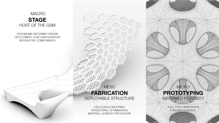
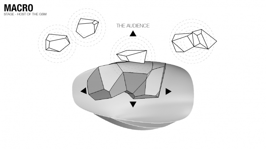
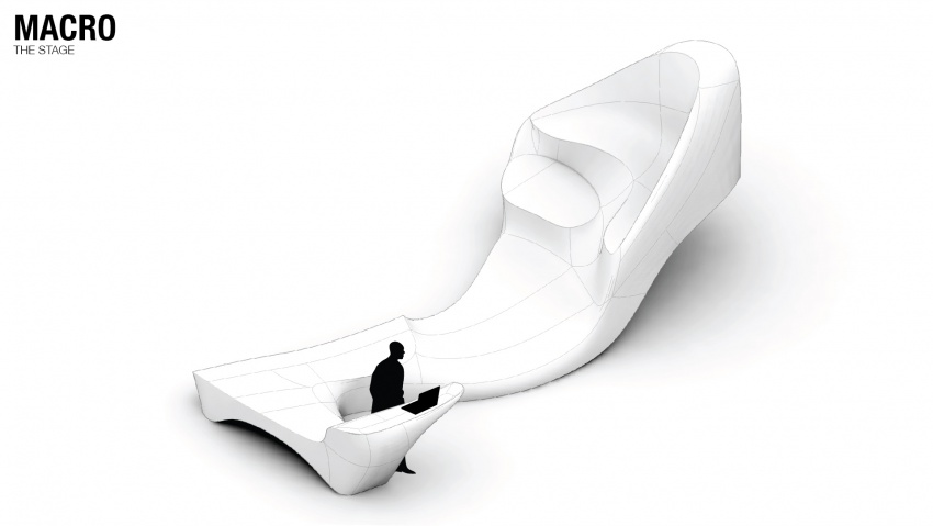
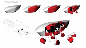
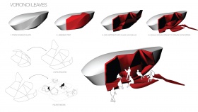
We started with the idea to create a stage that act as the Host of the GSM, the role is to blur the boundary of a stage, and hence getting the audience engaged into the event.
We've gone through a series of study and investigation, ending up with the three focus:
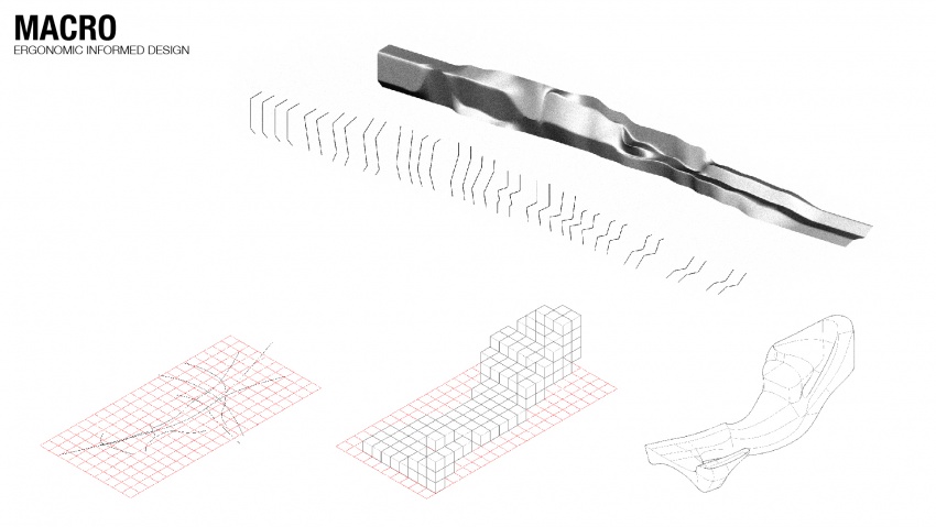
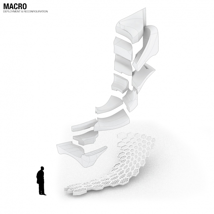
1/ Ergonomic informed Design 2/ Deployment & Reconfiguration 3/ Interactive components
//
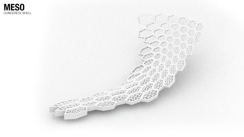
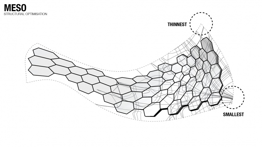
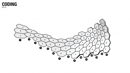
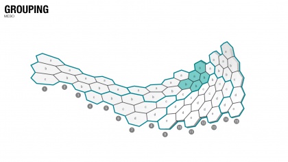
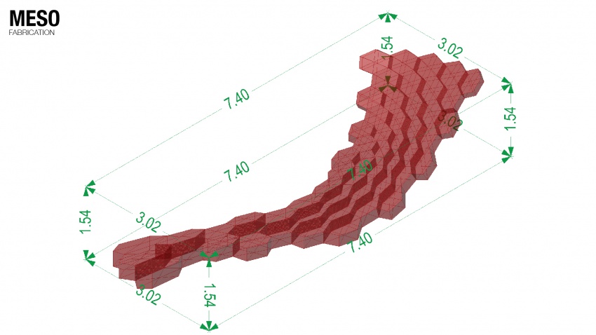
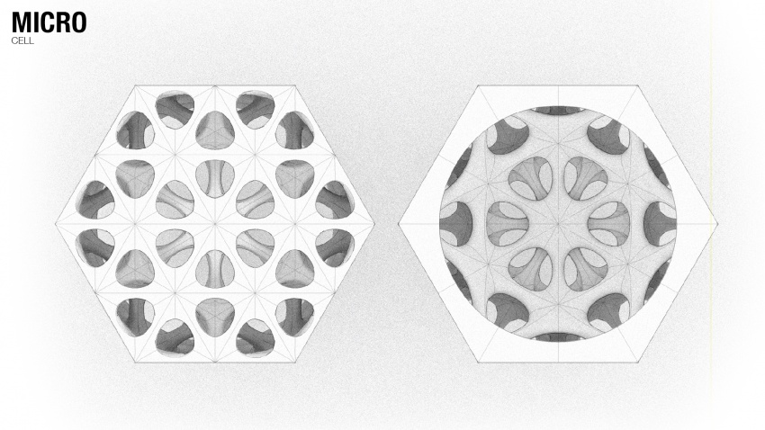
After defining the hexagonal pattern, we can use the volume of an individual cell to mill a mold of eps in which we pour concrete. The cells needs to be light but structural and according to the ergonomics, the top surface needs to be more solid in order to walk or sit on it. So our first direction is a cell of concrete that, as you near the bottom surface, will be more porous. The approach of milling is that we mount the piece of eps on a robotic arm and program the arm in such a way that the arm moves the eps according to the position of the fixed drill. In this way we can mill from all the directions except the bottom. Luckily this will not limit the design because of the higher level of porosity at the bottom. For the final result we aim for a straightforward design of the cell that exist out a milling method. So generate the tool paths and not receiving them from an already designed end result.
The first step is mount the eps on the robotic arm and use the hot wire cutter to cut away eps that is not within the boundary of the cell. Then we can use the tool paths to guide the robotic arm. The principle of the method is using the faces of the boundary in relationship to the cells center. Each evaluated point on the face, according to the distance to the center of the face, will inform the robot a depth it needs to drill. The closer to the center of the face the less deep it goes. So at the corners of the face the drill will reach the maximum length of the cells center. This principle will create a branching structure within the cell.
Cheung Cheuk Ming
Haris Grivokostopoulos
Max Kowalski
Maxime Selling
Tijs Niessen
